


Outdoor CATV Optical Node
Outdoor CATV Optical Node

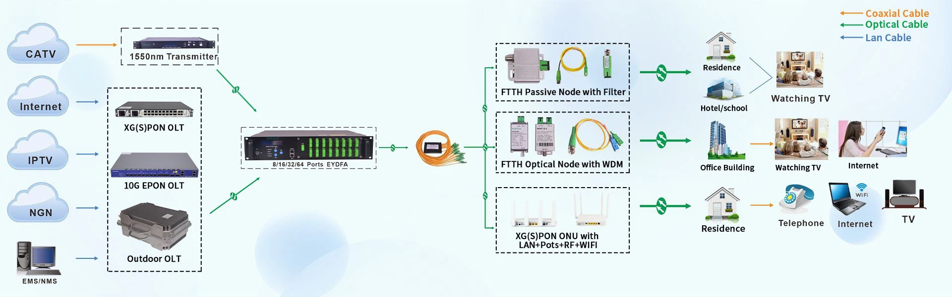
SR1012ST is our latest high-grade two-output outdoor CATV optical node. The pre-amplifier adopts full-GaAs MMIC, and the post-amplifier adopts GaAs module. Optimized circuit design, coupled with our 10 years professional design experience, makes the equipment achieve good performance indexes. Microprocessor control, digital display the parameters, the engineering debug is especially easy.
Performance Characteristics
High response PIN photoelectric conversion tube.
Optimized circuit design, with SMT process production, optimized signal path, makes the photoelectric signal transmission more smooth.
Specialized RF attenuation chip, with good RF attenuation and equilibrium linear, high accuracy.
GaAs amplifier device, power doubler output, with high gain and low distortion.
Single Chip Microcomputer (SCM) control equipment working, LCD display the parameters, convenience and intuitive operation, and stable performance.
Excellent AGC performance, when the input optical power range is -9~+2dBm, the output level keep unchanged, CTB and CSO basically unchanged.
Reserved data communication interface, can connect with the Ethernet transponder, access to network management system.
Return emission can select burst mode to sharply decrease the noise convergence and reduce the forepart receiver number.
Technique Parameter
Item | Unit | Outdoor CATV optical node | |||
Forward optical receiving part | |||||
Optical Parameters | |||||
Receiving Optical Power | dBm | -9 ~ +2 | |||
Optical Return Loss | dB | >45 | |||
Optical Receiving Wavelength | nm | 1100 ~ 1600 | |||
Optical Connector Type | FC/APC, SC/APC or specified by the user | ||||
Fiber Type | Single Mode | ||||
Link Performance | |||||
C/N | dB | ≥ 51 (-2dBm input) | |||
C/CTB | dB | ≥ 65 | Output Level 108dBμV EQ 6dB | ||
C/CSO | dB | ≥ 60 | |||
RF Parameters | |||||
Frequency Range | MHz | 45 ~862 | 45 ~1000 | ||
Flatness in Band | dB | ±0.75 | ±0.75 | ||
Rated Output Level | dBμV | ≥ 108 | ≥ 108 | ||
Max Output Level | dBμV | ≥ 114 | ≥ 112 | ||
Output Return Loss | dB | (45 ~550MHz)≥16/(550~1000MHz)≥14 | |||
Output Impedance | Ω | 75 | 75 | ||
Electronic Control EQ Range | dB | 0~15 | 0~15 | ||
Electronic Control ATT Range | dB | 0~20 | 0~20 | ||
Return Optical Emission Part | |||||
Optical Parameters | |||||
Optical Transmit Wavelength | nm | 1310±10, 1550±10 or specified by the user | |||
Output Optical Power | mW | 0.5, 1, 2 | |||
Optical Connector Type | FC/APC, SC/APC or specified by the user | ||||
RF Parameters | |||||
Frequency Range | MHz | 5 ~ 65 (or specified by the user) | |||
Flatness in Band | dB | ±1 | |||
Input Level | dBμV | 72 ~ 85 | |||
Output Impedance | Ω | 75 | |||
NPR Dynamic Range | dB | ≥15 (NPR≥30 dB) Use DFB laser | ≥10 (NPR≥30 dB) Use FP laser | ||
General Performance | |||||
Supply Voltage | V | A: AC (150~265)V; B: AC (35~90)V | |||
Operating Temperature | ℃ | -40~60 | |||
Storage Temperature | ℃ | -40~65 | |||
Relative Humidity | % | Max 95% no condensation | |||
Consumption | VA | ≤ 22 | |||
Dimension | mm | 260(L)* 200(W)* 130(H) | |||
Common Failure Analysis and Troubleshooting
Failure phenomenon | Failure cause | Solution |
After connecting the network, the image of the optical contact point has obvious netlike curve or large particles highlights but the image background is clean. | 1. The input optical power of the optical receiver is too high, make the output level of the optical receiver module too high and RF signal index deteriorate. 2. The RF signal (input the optical transmitter) index is poor. | 1. Check the input optical power and make appropriate adjustments to make it in the specified range; or adjust the attenuation of optical receiver to reduce the output level and improve index. 2. Check the front end machine room optical transmitter RF signal index and make appropriate adjustments. |
After connecting the network, the image of the optical contact point has obvious noises. | 1. The input optical power of the optical receiver is not high enough, results in the decrease of C/N. 2. The optical fiber active connector or adapter of the optical receiver has been polluted. 3. The RF signal level input the optical transmitter is too low, make modulation degree of the laser is not enough. 4. The C/N index of system link signal is too low. | 1. Check the received optical power of the optical contact point and make appropriate adjustments to make it in the specified range. 2. Recover the received optical power of the optical contact point by cleaning the optical fiber connector or adapter etc methods. Specific operation methods see “Clean and maintenance method of the optical fiber active connector”. 3. Check the RF signal level input the optical transmitter and adjust to the required input range. (When the input channels number less than 15, should higher than nominal value.) 4. Use a spectrum analyzer to check the system link C/N and make appropriate adjustments. Make sure the system link signal C/N﹥51dB. |
After connecting the network, the images of several optical contact points randomly appear obvious noises or bright traces. | The optical contact point has open circuit signal interference or strong interference signal intrusion. | 1. Check if there is strong interference signal source; change the optical contact point location if possible to avoid the influence of strong interference signal source. 2. Check the cable lines of the optical contact point, if there is shielding net or situation that the RF connector shielding effect is not good. 3. Tightly closed the equipment enclosure to ensure the shielding effect; if possible add shielding cover to the optical contact point and reliable grounding. |
After connecting the network, the images of several optical contact points appear one or two horizontal bright traces. | Power supply AC ripple interference because of the bad earth of equipment or power supply. | Check grounding situation of the equipment, make sure that every equipment in the line has been reliably grounding and the grounding resistance is﹤4Ω. |
After connecting the network, the received optical power of the optical contact point is unstable and has large continuous change. The output RF signal is unstable, too. But the detected output optical power of the optical transmitter is normal. | The optical fiber active connector types do not match, maybe the APC type connect to PC type, make the optical signal cannot normal transmission. The optical fiber active connector or adapter may be polluted seriously or the adapter has been damaged. | 1. Check the type of optical fiber active connector and adopt the APC type optical fiber active connector to ensure the normal transmission of optical signal. 2. Clean the polluted optical fiber active connector or adapter. Specific operation methods see “Clean and maintenance method of the optical fiber active connector”. 3. Replace the damaged adapter. |


Hot Tags: outdoor catv optical node, China, manufacturers, suppliers, factory, wholesale, 2 Way Return Path Outdoor Optical Receiver, HFC Optical Node, Fiber Optic Node CATV, 4 Way Return Path Outdoor Optical Receiver, 4 Way Outdoor Hfc Optical Node, Catv 4 Port Outdoor Optical Receiver
Next
No InformationYou Might Also Like


Send Inquiry